Nov 13, 2025
Content
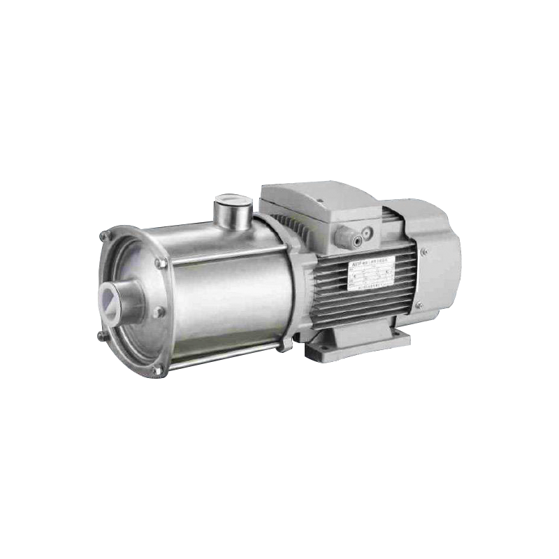
The operational principle of the horizontal multi-stage centrifugal pump is foundational to its widespread utility. At its core, this pump type utilizes multiple impellers arranged in series within a single casing to generate fluid pressure. Each impeller, housed in its own diffuser or volute, represents a single stage. As the fluid passes through the first impeller, its pressure increases. It is then directed to the inlet of the second impeller, where the pressure is boosted further. This process repeats sequentially through each subsequent stage, resulting in a cumulative pressure rise that a single-stage pump of comparable size could not achieve. The horizontal configuration, where the shaft is positioned parallel to the ground, offers distinct advantages in terms of stability, ease of maintenance, and alignment with standard motor designs. This design is particularly effective for applications requiring high-pressure outputs from a compact and robust footprint. The ability to generate significant head without resorting to an excessively large impeller diameter or extremely high rotational speeds makes it an energy-efficient and mechanically sound solution.
To fully appreciate the efficiency of these pumps, one must understand the role of each critical component. The synergy between these parts ensures reliable and continuous operation under demanding conditions.
The inherent design characteristics of horizontal multi-stage centrifugal pumps confer several compelling advantages that directly address the needs of modern water supply and processing facilities. These benefits are the primary drivers behind their growing market penetration.
In an era of rising energy costs and heightened environmental awareness, operational efficiency is paramount. Multi-stage pumps excel in this regard. By dividing the total pressure requirement across several smaller impellers, these pumps operate closer to their best efficiency point (BEP) for each stage compared to a single, large impeller struggling to achieve the same total head. This staged approach reduces internal recirculation, turbulence, and other hydraulic losses. The result is a significantly higher overall efficiency, which translates directly into lower electricity consumption. For municipal water supply systems and large-scale processing plants that run pumps continuously, even a small percentage gain in efficiency can lead to substantial cost savings and a reduced carbon footprint over the pump's lifecycle.
Many critical applications in water processing, such as reverse osmosis (RO) feed, boiler feed, and high-rise building water supply, require pressures that are impractical for standard single-stage centrifugal pumps. The multi-stage design is inherently suited for these high-head, low-to-medium flow rate duties. The ability to achieve pressures exceeding hundreds of bars within a relatively compact and space-saving horizontal footprint is a significant advantage. This compactness simplifies installation layout, reduces the required footprint in often-crowded plant rooms, and makes the pump easier to transport and handle compared to a large, single-stage vertical turbine pump or a positive displacement pump capable of similar output.
Reliability is non-negotiable in sectors where pump failure can lead to service disruption, process shutdown, or safety hazards. The robust construction of horizontal multi-stage pumps, with their heavy-duty shafts and multiple bearing supports, contributes to exceptional operational stability. They are less susceptible to vibration and shaft deflection than some alternative designs. Furthermore, the balanced radial hydraulic forces within a properly designed multi-stage pump minimize wear on bearings and seals, leading to longer mean time between failures (MTBF) and reduced maintenance costs. This predictable and dependable performance is highly valued in critical water infrastructure.
Potential users and specifiers often have specific technical questions when evaluating this pump technology for their applications. Providing clear, detailed answers is crucial for informed decision-making.
Noise pollution is a major concern, especially when equipment is installed in or near occupied spaces like urban residential or office buildings. The quest for a low noise horizontal multi-stage pump for urban buildings is a common driver in specification. The noise generated by a pump is primarily a result of hydraulic pulsation, mechanical vibration, and motor fan operation. Modern horizontal multi-stage pumps are engineered to address these sources comprehensively. Hydraulically, advanced impeller and diffuser designs ensure smooth, non-pulsating flow, which drastically reduces the excitation of acoustic frequencies. Mechanically, components are precision-balanced to levels that minimize vibrational energy at the source. Additionally, pump casings are often constructed with thicker walls and ribbing to dampen sound, and acoustically insulated jackets can be specified as an option. When comparing a standard pump to a low-noise optimized model, the difference is substantial. For instance, a standard pump might operate at 75 dB(A), whereas a model designed for low noise, utilizing these technologies, can achieve levels below 65 dB(A), which is a significant reduction in perceived loudness and is essential for meeting stringent building codes and ensuring occupant comfort.
Correctly sizing a pump for an application requires a precise understanding of its pressure requirements. A horizontal multi-stage pump pressure calculation guide is an invaluable tool for engineers. The total pressure, or head, that the pump must produce is not simply the vertical height; it is the sum of several components that represent the total energy required to move the fluid through the system. The fundamental equation is: Total Dynamic Head (TDH) = Static Head + Friction Head + Pressure Head. Static Head is the vertical difference in elevation between the source and the discharge point. Friction Head is the pressure loss due to the fluid's movement through pipes, fittings, and valves, and it increases with flow rate and pipe roughness. Pressure Head is the difference in pressure that must be maintained at the discharge vessel (e.g., a pressurized tank). For example, the requirement for a boiler feed pump would include a significant Pressure Head component. Misjudging any of these factors can lead to an undersized pump that cannot meet demand or an oversized pump that operates inefficiently and experiences premature wear.
Choosing the most suitable horizontal multi-stage centrifugal pump requires a careful analysis of the application's specific demands. A one-size-fits-all approach is ineffective and can lead to operational issues.
Identifying the best horizontal multi-stage pump for high-rise building water supply involves evaluating a set of critical performance and design parameters. The primary challenge in high-rise applications is generating sufficient pressure to serve fixtures on the top floors reliably, which often requires a pump capable of producing very high heads. Furthermore, these pumps must be energy-efficient due to their continuous operation, compact to fit into limited mechanical room spaces, and exceptionally quiet to prevent disturbance. Key selection criteria include the maximum total head required, the desired flow rate, energy efficiency class (e.g., IE3, IE4), noise level certifications, materials of construction (e.g., stainless steel for potable water compatibility), and the availability of integrated variable frequency drives (VFDs) for pressure stabilization and additional energy savings. A comparison between a basic model and a premium model tailored for high-rises would reveal significant differences.
| Feature | Standard Model | Premium High-Rise Model |
|---|---|---|
| Maximum Head | Up to 150 meters | Up to 400 meters or more |
| Efficiency | Standard efficiency (e.g., IE2) | Premium efficiency (e.g., IE4) |
| Noise Level | ~70-75 dB(A) | < 65 dB(A) |
| Control System | Fixed speed / basic starter | Integrated VFD for constant pressure |
| Casing Material | Cast Iron | Stainless Steel (CD4MCu, etc.) |
Proactive maintenance is the key to maximizing the service life and reliability of any critical asset. Adhering to a well-defined horizontal multi-stage centrifugal pump maintenance schedule prevents unexpected downtime and costly repairs. Maintenance activities can be categorized into daily, weekly, monthly, and annual tasks. A comprehensive schedule includes regular checks of vibration levels, bearing temperatures, and seal integrity. It also mandates periodic actions such as lubricating bearings, checking and re-torquing alignment between the pump and motor, and eventually, the overhaul of the entire rotating assembly. The following is a generalized outline of a maintenance schedule.
Beyond routine maintenance, long-term reliability is influenced by the initial pump selection, installation quality, and operational practices. Understanding the full lifecycle context is essential.
Vibration is one of the most telling indicators of a pump's health. Effectively troubleshooting horizontal multi-stage pump vibration issues requires a systematic approach to diagnose and rectify the root cause, which can be mechanical, hydraulic, or operational in nature. Excessive vibration accelerates bearing failure, damages mechanical seals, and can lead to catastrophic shaft failure. A step-by-step troubleshooting process begins with the most common and easily addressable causes before moving to more complex internal issues. The table below contrasts common symptoms with their potential causes and recommended corrective actions.
| Symptom | Potential Cause | Corrective Action |
|---|---|---|
| High vibration at running speed | Rotor imbalance, Misalignment, Worn bearings | Re-balance rotor, Re-align pump and motor, Replace bearings |
| Vibration that changes with flow | Operating far from BEP, Cavitation, Internal recirculation | Throttle discharge valve to shift operating point, Check for suction restrictions, Ensure NPSHa > NPSHr |
| Vibration at vane-pass frequency | Impeller/diffuser interaction, Impeller damage | Inspect and replace damaged impeller, Check impeller-to-diffuser clearance |
In water processing applications, the fluid is not always pure. It may contain chemicals, suspended solids, or have an aggressive pH level. The longevity of the pump is heavily dependent on selecting appropriate materials for its wetted parts to resist corrosion (chemical attack) and erosion (physical wear). For standard clean water, cast iron casings and bronze impellers may be sufficient. However, for seawater, brackish water, or chemically treated water, stainless steels like 304SS or 316SS are necessary. For highly corrosive fluids or those with high chloride content, duplex or super duplex stainless steels offer superior resistance. In applications with high suspended solids, such as slurry handling in certain processing stages, materials with high hardness and erosion resistance, like high-chrome white iron or specialized coatings, are employed to extend the life of impellers and casing wear rings. The correct material selection is a critical investment that prevents premature failure and ensures consistent performance.
Related Products
Contact us
Headquater Address
Room 901, Building 17, Lane 1088, Shen Hong Road, Minhang District, Shanghai
Factory Address
No. 1, Mingxing North Road, Tech Innovation Park, Jianhu County, Yancheng, Jiangsu, P. R. China
Amy@mxwatersupply.com
Amy@mxwatersupply.com
Telephone(Whatsapp/Wechat)
+86-18051685983
QR CODE
 English
 Français


