Oct 27, 2026
By the fifth year of service, a 14-story apartment building had logged two pump-seal failures and a pump start every forty seconds through the night. Larger pumps only made the hunting worse. The fix was an integrated booster pump system: a factory-assembled package of multistage pumps, pressure sensors, a diaphragm tank, VFD drives, and a sequencing controller, tested as one hydraulic machine.
That distinction changes the outcome. A single engineered package is sized to a known demand profile, stabilized by a pressure-maintenance tank, and controlled so pumps stay in their efficient range. Most buildings above four stories need boosting; the real question is which design choices deliver stable pressure without wasting energy.
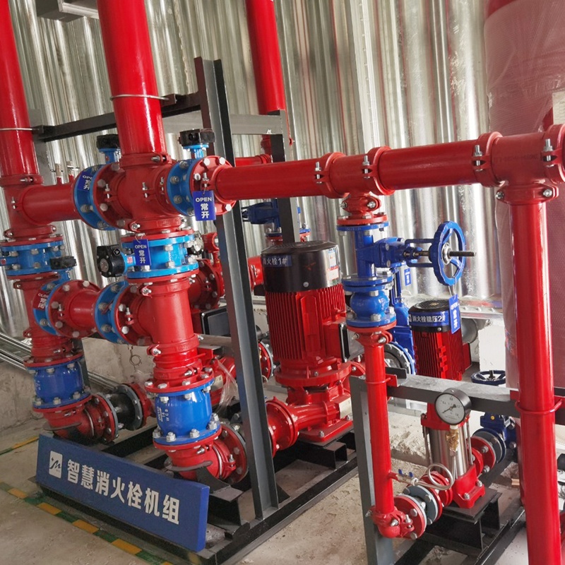
An integrated booster pump system is a pre-engineered, factory-assembled unit that raises incoming water pressure to a building's service level. "Integrated" means the pumps, tank, transducers, drives, valves, and controller are piped and programmed as one system, so pressure regulation and sequencing come from a single logic source.
Content
A complete integrated booster pump system has four functional groups: the pumping stage, the pressure-maintenance stage, the sensing-and-control stage, and the hydraulic isolation stage.
In a typical mid-rise installation, the pumping stage is two to four vertical multistage centrifugal pumps in a duty/standby or duty/assist arrangement. The maintenance stage is a small diaphragm tank that absorbs start-up surges and lets the system sleep. The control stage couples a discharge pressure transmitter to a VFD and a programmable controller. The hydraulic stage ties everything together with check valves, isolation valves, flexible connectors, and a common header.
| Component | Role in the system |
| Vertical multistage pumps | Generate the required head; staging matches capacity to demand. |
| Diaphragm pressure tank | Absorbs pressure spikes and provides low-flow sleep capacity. |
| Pressure transmitter | Samples discharge pressure constantly for closed-loop VFD control. |
| VFD and controller | Vary pump speed, rotate duty pumps, and manage alarm conditions. |
| Valve manifold | Prevents reverse flow and permits servicing without draining the system. |
Size the system to peak-hour flow and to the head required at the highest fixture, never to the pipe diameter or the old pump's nameplate.
Unusual demand profiles, such as hotels, hospitals, or buildings with process loads, deserve a second check. A manufacturer's engineering support team can verify the selection against actual fixture counts before the order is placed.
The VFD and its control algorithm determine most of the energy and pressure-stability results of an integrated booster pump system.
A fixed-speed pump responds to an opening tap by sliding down its curve, so pressure falls as flow rises. A VFD-driven pump holds the discharge setpoint by raising speed during the morning peak and dropping it at night, when flow can fall below 10 percent of peak. The chart shows relative annual pump energy for four control modes under the same partial-load profile.
Multi-pump sequencing on VFDs cuts annual pump energy 30-45 percent versus throttled constant-speed operation and removes the inrush current that wears out contactors. A factory-tested unit such as the VFD-controlled constant-pressure booster system arrives with sequencing logic programmed and setpoints field-adjustable, so commissioning takes hours, not days.
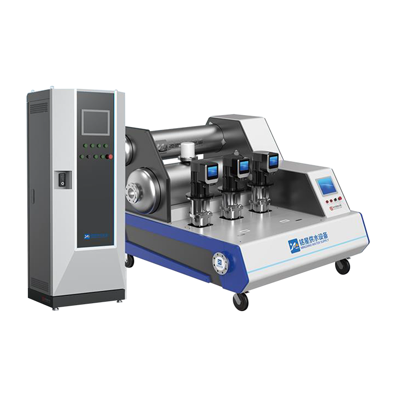 VFD-Controlled Constant-Pressure Booster System with Factory-Tested SequencingThis variable-frequency booster package comes with sequencing logic pre-programmed and field-adjustable setpoints, so installation and commissioning can be completed in hours. It suits projects needing energy-efficient water pressure boosting with minimal on-site tuning.View Product →
Choose the configuration by suction conditions and footprint: tank-type systems buffer unstable municipal supply, box-type systems protect the public main from negative pressure, and skid systems fit existing mechanical rooms.
Tank-type non-negative pressure systems hold a buffer tank and use municipal pressure as suction assist, suiting fluctuating inlet mains. Box-type systems draw directly from the main with a vacuum-prevention valve, a requirement under strict utility rules. Skid packages without a tank suit retrofits where floor space is committed.
 Digital Full-Frequency Box-Type Non-Negative Pressure Water Supply SystemA tank-type booster with full variable-speed drive and differential compensation, featuring intelligent monitoring, stainless steel tank, and UV disinfection. It supports one-in-use backup modes and remote fault alarms for reliable municipal water boosting.View Product →
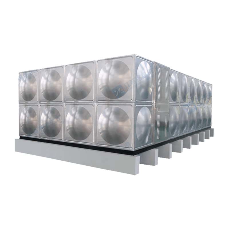
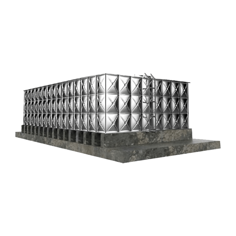
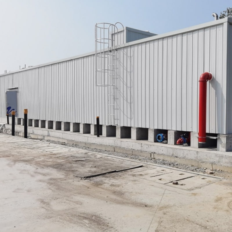
When a project needs daily supply and fire reserve, a combined domestic-and-fire pumping station shares one storage volume with segregated draw-off and dedicated pump sets, cutting civil works by roughly 25-30 percent. Prefabricated integrated pump stations of this type are referenced in standard atlas 18CS01 and technical specification CECS623-2019.
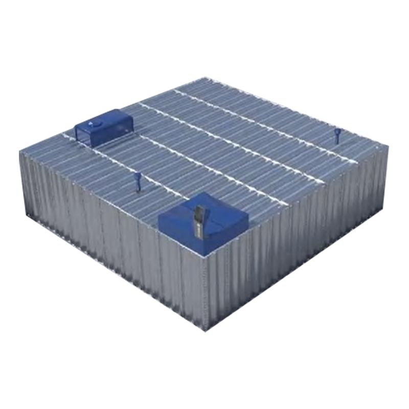 Integrated Domestic and Fire-Protection Pumping Station with Shared StorageThis prefabricated station combines daily water supply and fire reserve in one modular enclosure, with dedicated pump sets and segregated draws to cut civil works by about 25-30 percent. It suits residential communities, industrial plants, and similar facilities.View Product →
Most field failures are control and selection failures: wrong tank sizing, transducer drift, and disabled pump alternation cause the majority.
These patterns appear repeatedly in field notes on the common fault patterns of integrated box-type pump systems, and nearly all are avoidable.
A two- to four-pump vertical multistage system adds 0.20-1.60 MPa at the discharge, depending on the number of stages. For normal building duty, set the discharge to hold 0.30-0.45 MPa so the highest fixtures still receive at least 0.15 MPa under full flow.
Yes, with non-negative pressure protection. A box-type or tank-type non-negative pressure station monitors suction pressure and throttles flow before the inlet drops below the utility's minimum. Where regulations demand a physical break, use a suction-tank configuration instead.
Quarterly for commercial duty: verify setpoints, inspect the tank pre-charge, test alternation, and measure VFD output current. Annually, add transducer calibration, coupling torque checks, and inlet-strainer cleaning. Systems on poor-quality water need the same steps monthly.
Yes, from a shared tank with segregated pump sets and separate discharge headers, when the design follows fire codes. A combined station of this type cuts footprint and civil cost but must use dedicated fire pumps and a controller with approved alarm interfacing.
Whether the project is a failing constant-speed retrofit or a new tower with a tight footprint, the integrated approach pays twice: once in the equipment room, where a factory-assembled system commissions in days, and again on the utility statement, where speed control and sequencing appear as a smaller line item.
Related Products

Contact us
Headquater Address
Room 901, Building 17, Lane 1088, Shen Hong Road, Minhang District, Shanghai
Factory Address
No. 1, Mingxing North Road, Tech Innovation Park, Jianhu County, Yancheng, Jiangsu, P. R. China
Amy@mxwatersupply.com
Amy@mxwatersupply.com
Telephone(Whatsapp/Wechat)
+86-18051685983
QR CODE

 English
 Français