Oct 23, 2026
Ask five contractors to specify a non negative pressure booster system and you will get five different suction limits. The hardware looks the same everywhere: pumps coupled straight to the municipal main, a controller watching suction pressure, and no break tank in between. Where the specifications diverge is the point at which the pump is allowed to stop pulling.
The intent behind the design is simple. The set draws water directly from the distribution main and adds only the pressure the building needs, so the main keeps its own pressure and the building does not store water it will not use within a day. Every other component exists to protect the suction side.
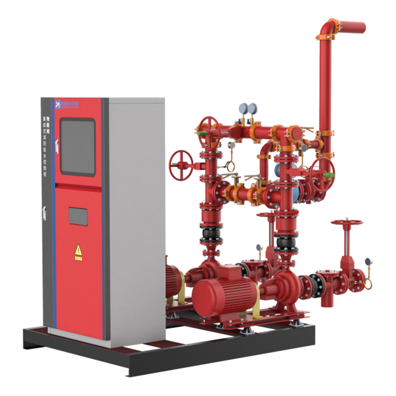
A typical unit pairs two to four vertical multistage pumps with full variable frequency control, a steady-flow controller or vacuum suppressor, pressure transmitters on both sides of the set, and a small diaphragm vessel that absorbs start-stop surges. Response time separates good installations from average ones: a set that needs three seconds to react to a pressure dip has already pulled the branch main negative on a busy 200 mm line.
Content
A non negative pressure booster system fits when the municipal main can still deliver the design flow at roughly 0.15 MPa or more during the worst hour of the day, when the project does not need stored fire water, and when plant room space is scarce. When any of those three conditions fails, a break tank arrangement remains the correct answer.
Projects caught between those two categories usually land on a tank-type set with voltage stabilizing control, which keeps a small controlled volume in the circuit without behaving like a full storage tank. It is the practical compromise for retrofit work where main pressure is adequate on paper but uneven in practice.
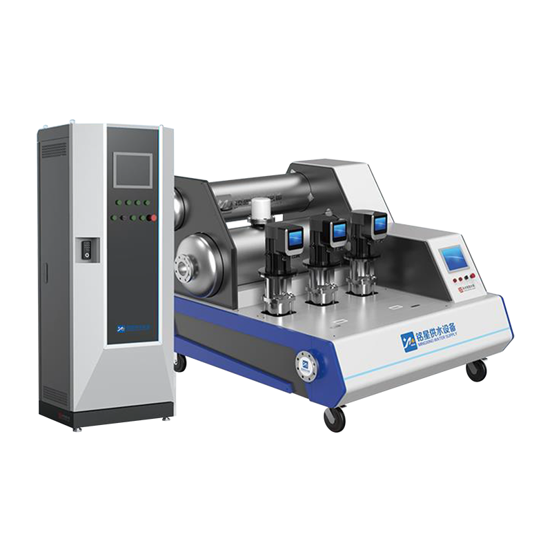
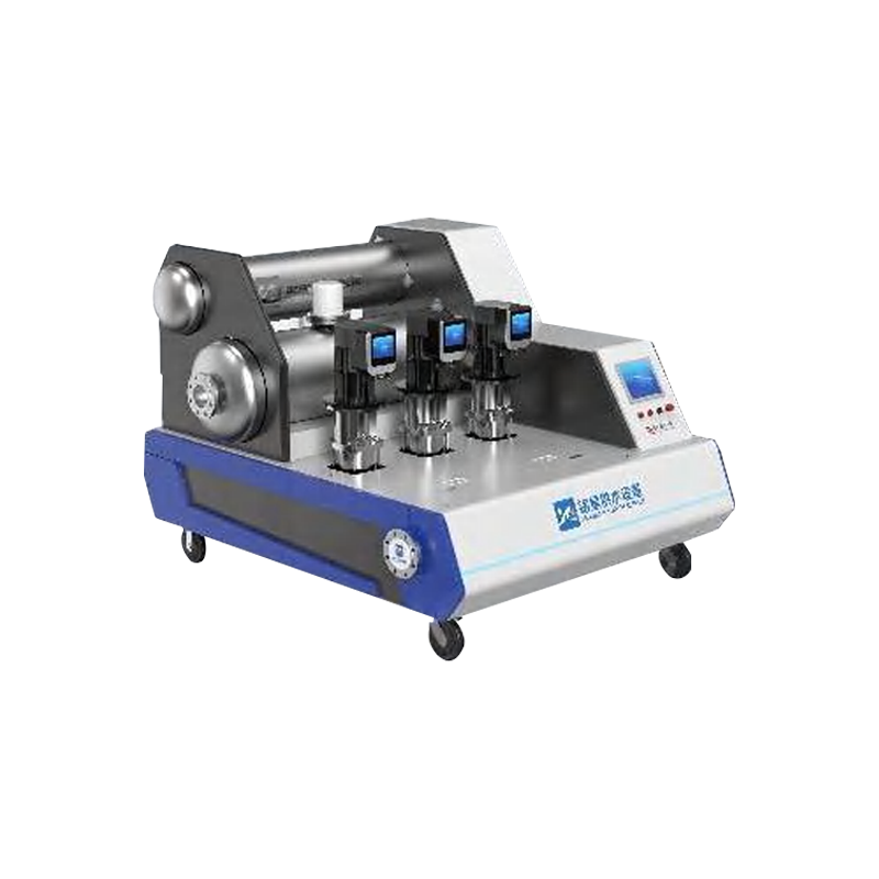 Digital Full-Frequency Voltage-Stabilizing Tank-Type Non-Negative-Pressure Water Supply EquipmentA tank-type non-negative-pressure set with full variable-frequency control, stainless-steel constant-flow tank, and remote monitoring for uneven mains pressure retrofit projects.View Product →
Size the flow at 1.2 times the peak hourly demand, the head as static lift plus 0.15 to 0.20 MPa of pipework loss plus 0.10 MPa of residual at the highest fixture, and set the suction cut-out 0.02 MPa below the lowest main pressure you have actually measured. A guessed mains figure is the single most common cause of a booster that trips every morning.
| Parameter | Typical design value | Consequence if it is missed |
| Design flow | 1.2 times peak hourly demand | Short cycling and pressure dips at peak hour |
| Total head | Static lift plus 0.15 to 0.20 MPa losses plus 0.10 MPa residual | Upper floors run below the required pressure |
| Suction threshold | 0.02 MPa below the lowest recorded dynamic pressure | Nuisance trips or stress on the distribution main |
| Pump staging | Three pumps, two duty plus one standby | No redundancy during service or failure |
| Control mode | Full variable frequency on every pump | Hunting between stages and higher energy use |
| Buffer vessel | 50 to 150 L diaphragm vessel | Pressure spikes on each pump start |
Measure before you size. A seven-day log at fifteen-minute intervals, taken at the same tapping point the booster will use, tells you more than any nameplate mains figure. Where that log shows short dips below the protection threshold, a differential compensation box-type non negative pressure set bridges the gap from a small break chamber instead of stopping the pumps.
 Digital Full-Frequency Differential Compensation Box-Type Non-Negative-Pressure Water Supply SystemA direct-coupled, tankless booster with differential compensation and full variable-frequency control for high-rise constant-pressure supply where measured mains dips occur.View Product →
Full variable frequency control holds specific energy use near 0.27 kWh per cubic metre in typical residential duty, against roughly 0.42 kWh for a roof tank feeding a fixed-speed pump set. Two effects drive that difference, and only one of them is the drive itself.
The first effect is the head you never add. A roof tank scheme usually needs an extra 0.30 to 0.35 MPa to lift water to the tank and then re-pressurise the riser below it, and a direct-coupled set skips both steps. The second effect comes from the affinity law: at 80 percent of rated speed, shaft power falls to roughly half, which is why a single VFD driving one staging pump rarely matches a fully speed-controlled set.
Commissioning a non negative pressure booster system is a suction-side exercise. Get the suction behaviour right and discharge pressure follows; skip it and the set will trip whenever the neighbourhood wakes up.
Routine work after handover is short, but it is not optional.
The control behaviour behind those checks is explained further in this note on how VFD control stabilises constant pressure booster systems. Factory-assembled stations, wired and pressure-tested before shipment, reduce step two on site to a single connection check.
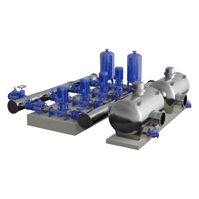 Digital Fully Variable-Frequency Tank-Type Non-Negative-Pressure Pump StationA tank-type non-negative-pressure pump station with independent VFD control and intelligent monitoring for constant-pressure water supply.View Product →
A conventional booster set draws from a break tank, so the pumps never touch the municipal main and suction pressure is not a design constraint. A non negative pressure booster system draws directly from the main, which removes the tank room and the cleaning regime but makes suction protection the governing design task. Conventional sets tolerate a weak main; direct-coupled sets require a measured one.
Not on its own. Fire demand requires a stored reserve that satisfies the local code, so most projects combine a domestic direct-boost set with a separate fire reserve tank and a dedicated fire pump set, or consolidate both duties in one domestic and fire pumping station sharing a single plant room.
The controller reduces pump speed first, then stops the set and waits for pressure to recover before restarting. Modern controllers also log each event with a timestamp, which turns a nuisance complaint into a measurable mains problem. A differential compensation variant bridges short dips from a small buffer volume instead of stopping.
Roughly 40 to 60 percent less than a break tank and booster arrangement serving the same demand. A three-pump set handling 36 cubic metres per hour for a 30-storey tower typically fits within 6 to 9 square metres, including one metre of maintenance clearance at the front of the skid.
If you already have a seven-day pressure log, send it to the engineering team through our contact page before the equipment list is frozen. Suction data decides the configuration far more often than building height does.
Related Products

Contact us
Headquater Address
Room 901, Building 17, Lane 1088, Shen Hong Road, Minhang District, Shanghai
Factory Address
No. 1, Mingxing North Road, Tech Innovation Park, Jianhu County, Yancheng, Jiangsu, P. R. China
Amy@mxwatersupply.com
Amy@mxwatersupply.com
Telephone(Whatsapp/Wechat)
+86-18051685983
QR CODE

 English
 Français