Jul 15, 2026
Content
A circulation pump moves fluid continuously through a closed loop system rather than transferring it from one point to another and stopping. Its job isn't to move fluid from a source to a destination the way a transfer pump does — it's to keep fluid actively cycling through a system so temperature, pressure, or chemical treatment stays consistent throughout the loop rather than settling into stagnant, uneven pockets.
This function shows up across a wide range of systems. In hydronic heating and cooling, a circulation pump keeps hot or chilled water moving between a boiler or chiller and the radiators, floor loops, or air handlers distributed through a building — without continuous circulation, heat would only reach whatever's closest to the source, leaving distant zones cold. In domestic hot water systems, a dedicated circulation pump keeps hot water constantly present in the pipe run to fixtures, eliminating the wait for hot water to travel from the tank every time a tap is opened.
The same principle applies in industrial and process settings — cooling loops for machinery, chemical treatment systems that need consistent mixing, and aquarium or pond filtration systems all rely on circulation pumps to keep fluid moving through filters, heat exchangers, or treatment stages repeatedly rather than passing through just once. Because the pump is typically working against a closed loop's internal resistance rather than lifting fluid to a significant height or moving it long distances, circulation pumps are generally sized around flow rate and the loop's resistance to flow, not the high-pressure or high-lift specifications that transfer pumps are built around.
There's also an energy dimension worth understanding: because a circulation pump runs against a closed loop, the fluid it moves eventually returns to the pump's inlet rather than being lost to the system, so the pump isn't fighting gravity or elevation change the way a pump lifting water to a rooftop tank would be. Its main job is simply overcoming friction loss as fluid moves through pipes, fittings, and heat exchangers — which is why circulation pump energy consumption is so closely tied to pipe sizing and system design, not just the pump's own efficiency rating.
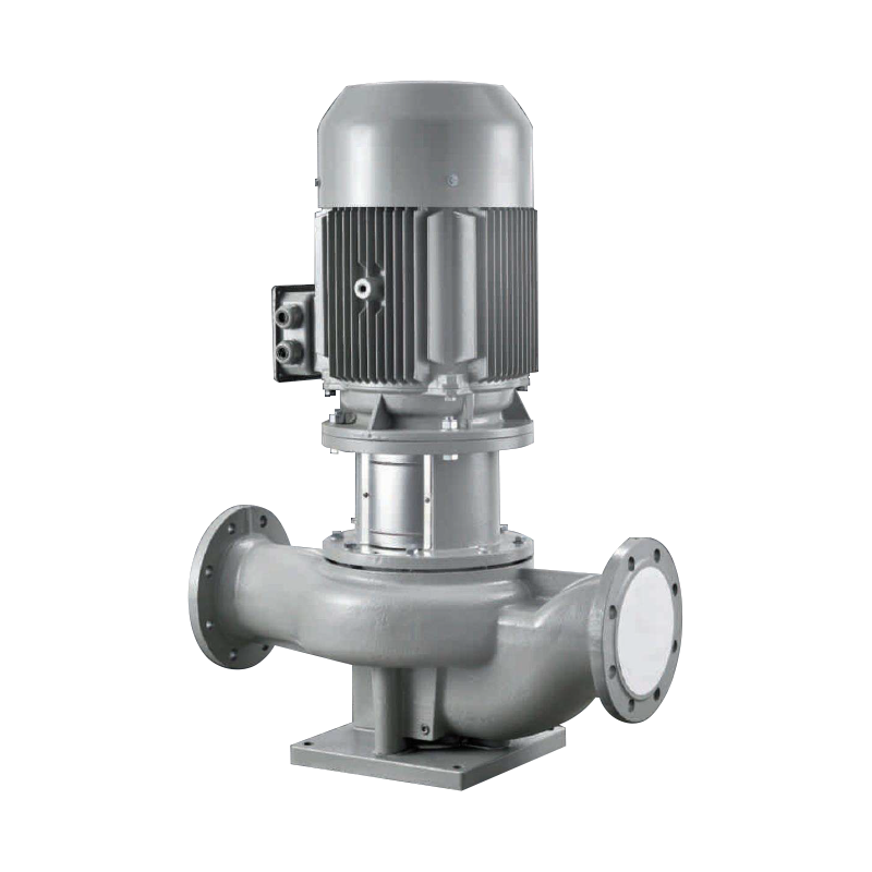
Circulation pumps split into a few distinct construction categories, and the choice between them affects maintenance needs, noise level, and long-term reliability more than raw flow performance:
| Type | How It's Built | Trade-offs |
|---|---|---|
| Wet rotor | Motor rotor is submerged in the pumped fluid itself, which lubricates and cools it | Quiet, low-maintenance, but limited to lower-pressure, smaller-scale applications |
| Dry rotor | Motor is fully sealed and separated from the fluid by a shaft seal | Higher efficiency and pressure capability, but the shaft seal is a wear point requiring periodic maintenance |
| Fixed speed | Runs at one constant speed whenever powered on | Simple and inexpensive, but can waste energy circulating at full flow when the system doesn't need it |
| Variable speed | Electronically adjusts motor speed based on system demand or a control signal | Meaningfully lower energy use across a heating season, at a higher upfront equipment cost |
Wet rotor designs dominate residential and light commercial hydronic circulation specifically because the fluid itself handles lubrication and cooling, eliminating the need for a mechanical shaft seal — which is usually the first component to wear out and leak on a dry rotor pump. Variable-speed wet rotor circulators have become the default recommendation in most modern heating system designs, since they automatically reduce speed (and energy use) once a zone reaches its target temperature rather than continuing to push full flow unnecessarily.
An inline pump is defined by its physical installation rather than a unique internal mechanism — it's mounted directly within a straight run of pipe, with the inlet and outlet aligned on the same axis, rather than sitting off to the side with separate suction and discharge piping bent at an angle. This is what "inline" refers to: the pump becomes a segment of the pipe itself instead of a separate unit connected by additional fittings and elbows.
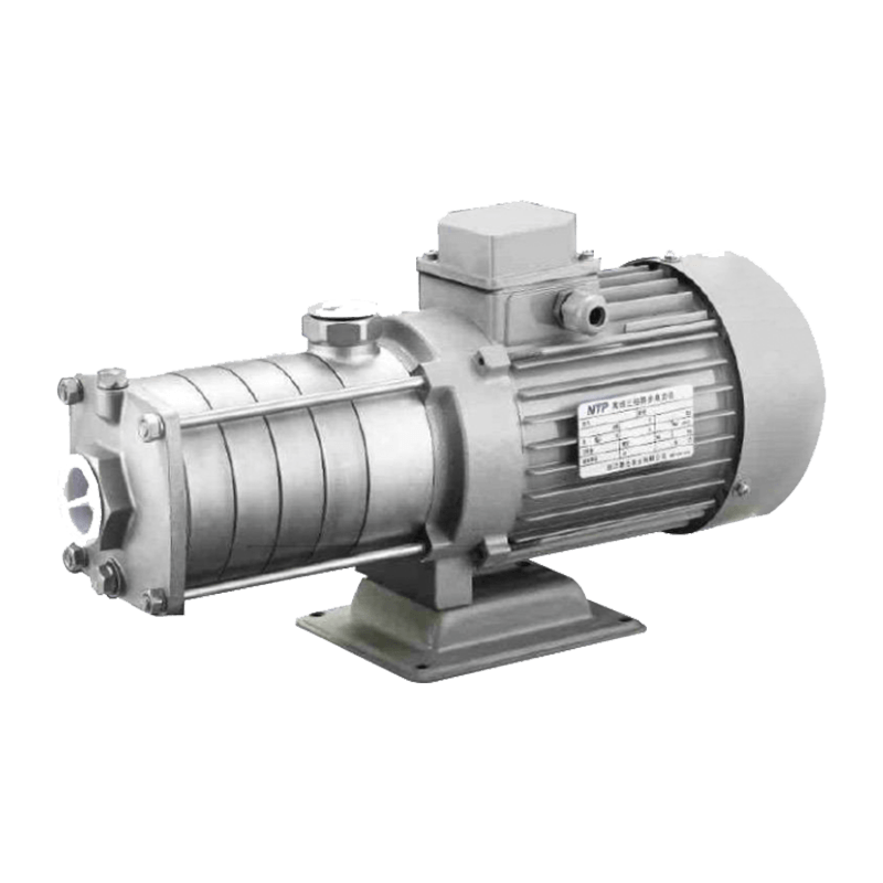
Internally, most inline pumps use a centrifugal mechanism: an electric motor spins an impeller inside the pump housing, and the impeller's rotation flings fluid outward through centrifugal force, which converts the motor's rotational energy into fluid velocity and pressure. Fluid enters through the pump's center (aligned with the pipe's flow direction) and exits radially before being redirected back into the outlet, all within a housing compact enough to sit directly in the pipeline.
The impeller design itself has a meaningful effect on performance characteristics. A single-stage impeller pushes fluid through one rotation cycle and suits lower-pressure applications like residential circulation, while multi-stage inline pumps stack several impellers in series, with each stage adding incremental pressure to the fluid before passing it to the next — this staged approach lets a compact inline housing achieve considerably higher pressure output than a single-stage design could, which is why multi-stage inline pumps show up in applications like water pressure boosting for taller buildings despite sharing the same fundamental inline mounting concept as a small residential circulator.
The practical advantage of this inline design is installation simplicity and space efficiency — because the pump sits directly in the pipe run rather than requiring a separate mounting base and additional connecting pipework, it takes up less physical space and involves fewer joints and fittings than an equivalent end-suction pump mounted off to the side. Fewer joints also means fewer potential leak points, which is part of why inline pumps are a common choice specifically for circulation applications where the pump needs to be embedded unobtrusively within an existing pipe run, such as a hydronic heating loop running through a mechanical room.
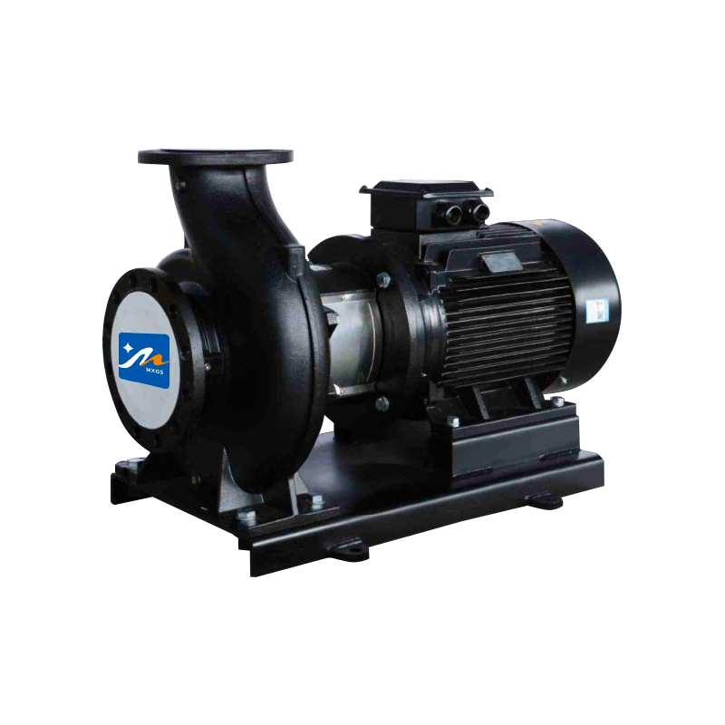
It's worth contrasting the inline mounting style against the more traditional end-suction pump configuration to see exactly what the inline design trades away and gains. An end-suction pump has its inlet centered on one end of the housing and its outlet exiting perpendicular to that, typically mounted on a baseplate with the motor coupled to the pump via a separate shaft and coupling.
This configuration generally allows for larger, more serviceable pumps — the motor and pump can be decoupled and worked on somewhat independently, and larger impeller sizes are easier to accommodate in an end-suction housing than in a compact inline body. The trade-off is a larger physical footprint, a dedicated mounting pad or baseplate, and more connecting pipework and fittings between the pump and the main pipe run, each of which is an additional potential leak point and adds to installation labor and cost.
In practice, the choice tends to fall out naturally from the application's scale — small to mid-sized circulation loops, where the pump just needs to overcome moderate friction loss in a closed loop, are well served by compact inline pumps, while larger industrial process pumping, especially where higher flow rates or easier serviceability matter more than compact footprint, more often uses end-suction or other baseplate-mounted configurations.
These two terms describe different aspects of a pump — purpose versus mounting configuration — and in practice they overlap heavily rather than describing competing pump categories. Most dedicated circulation pumps, particularly the smaller units used in residential hydronic heating and domestic hot water recirculation, are built as inline pumps specifically because the closed-loop, continuous-duty nature of circulation work suits the compact, low-maintenance inline format well.
Not every inline pump is used for circulation, though — the inline mounting style shows up in other applications too, such as booster pump stations that boost pressure in a straight pipe run without necessarily forming a closed circulation loop. The distinction is worth keeping in mind mainly because a product listed as an "inline pump" is describing how it mounts, not automatically confirming it's rated for the continuous, often 24/7 duty cycle that circulation applications typically demand — that's a separate specification worth checking against the motor and bearing design rather than assuming from the inline label alone.
Both terms show up across a fairly consistent set of real-world systems, though the specific pump size and construction varies enormously between them:
Selecting the right circulation or inline pump comes down to matching two core specifications against the system it's serving: required flow rate (how much fluid volume needs to move through the loop) and head pressure (how much resistance the pump needs to overcome from pipe friction, fittings, and any elevation change in the loop). Oversizing a circulation pump doesn't just waste energy — excess flow velocity through pipes and fittings can increase noise and, over time, contribute to erosion-related wear inside the piping system.
For hydronic heating specifically, pump sizing is typically derived from the heat output required and the temperature drop the system is designed around, translated into a required flow rate, then matched against the total friction loss of the piping circuit at that flow rate to find a pump that can deliver adequate flow against that resistance. Getting this calculation wrong in either direction causes real problems: undersizing leaves distant zones under-heated because the pump can't push enough flow against the loop's resistance, while oversizing wastes energy and can introduce flow noise that's often mistaken for a mechanical fault.
Circulation and inline pumps are generally low-maintenance by design, but a few components are worth periodic attention. On dry rotor designs, the mechanical shaft seal is the most common wear item — seal degradation typically shows up as slow weeping or dripping at the pump housing before it becomes a more significant leak, so catching early seal wear during routine inspection avoids a more disruptive failure later.
Air trapped in the system is one of the most common operational issues, particularly after initial installation or after any maintenance that opens the loop — trapped air causes the pump to run noisily, lose priming, or circulate inconsistently, which is why most circulation pumps include a bleed valve or air vent point specifically to purge trapped air during commissioning and periodically afterward.
Mineral scale buildup inside the pump housing and impeller is another long-term consideration, especially in hard water regions or systems that see significant makeup water addition over time — scale reduces impeller efficiency and can eventually cause the pump to seize, which is why some systems incorporate water treatment or periodic descaling as part of routine maintenance rather than waiting for pump performance to visibly degrade.
Related Products

Contact us
Headquater Address
Room 901, Building 17, Lane 1088, Shen Hong Road, Minhang District, Shanghai
Factory Address
No. 1, Mingxing North Road, Tech Innovation Park, Jianhu County, Yancheng, Jiangsu, P. R. China
Amy@mxwatersupply.com
Amy@mxwatersupply.com
Telephone(Whatsapp/Wechat)
+86-18051685983
QR CODE

 English
 Français