Oct 20, 2026
During a start-up test at a 12,000 m2 logistics center, the fire fighting water supply system passed every static calculation but failed under live demand. As the main pump ramped up, suction pressure at the inlet flange dropped from 0.38 MPa to 0.09 MPa in under 60 seconds, the low-suction cut-out tripped, and the standby pump refused to take over. The cause was not pump capacity: a partially open butterfly valve and a clogged strainer on the tank outlet created a vortex restriction that starved the pump. That failure illustrates the central rule of fire water system design - every component, from the tank outlet to the most remote sprinkler, belongs to one continuous hydraulic circuit.
A fire fighting water supply system is the integrated assembly of water storage, pumping equipment, piping, valves, and instrumentation that delivers the flow, pressure, and duration required by a building's fire suppression appliances. This guide covers how those components work together and where the numbers come from.
Content
A fire fighting water supply system must deliver a verified flow and pressure at every discharge point for a prescribed duration, automatically, without operator action.
Three parameters govern the design: flow, pressure, and duration. Flow comes from the highest simultaneous demand - sprinkler density times design area, plus hose and standpipe demand. Pressure is calculated at the most remote sprinkler by adding elevation, friction, and device losses to the sprinkler's minimum working pressure. Duration follows the occupancy hazard class and the governing code.
Codes such as NFPA 13 and NFPA 20 set the minimums, but a compliant design can still fail if the hydraulic balance across the package is wrong. Suction-side vortexing, oversized check valves, and incorrectly selected strainers are the most common field defects found during pump tests.
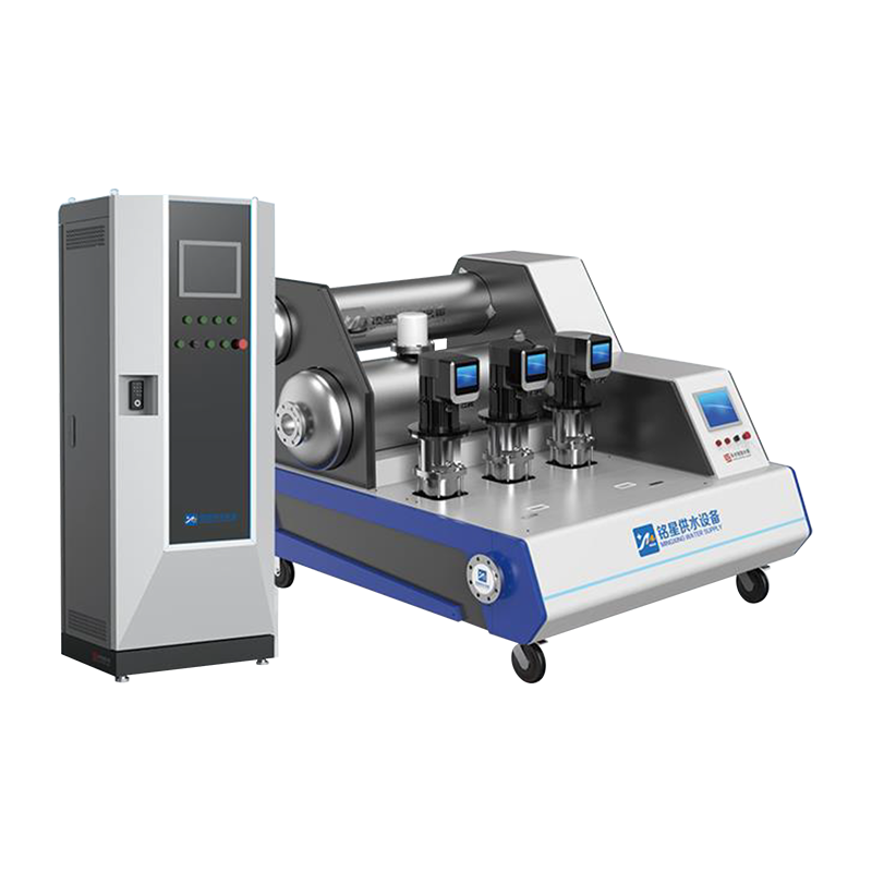
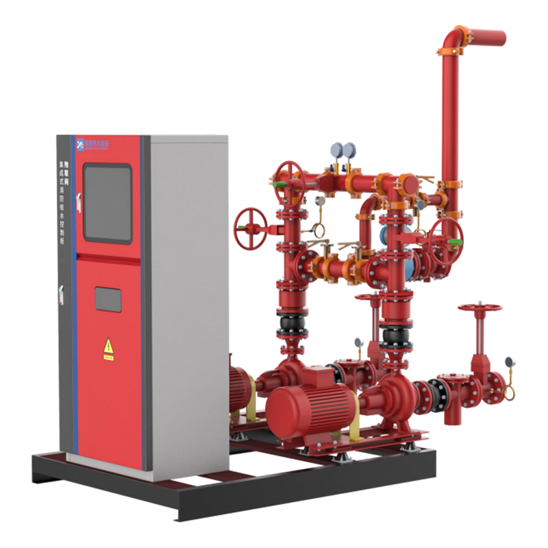 Smart Fire-Fighting Water Supply System with Remote MonitoringThis integrated fire water supply unit offers cloud-based monitoring of tank levels, pump status, and power parameters, which helps operators verify that the calculated fire reserve volume is actually available and managed correctly.View Product →
Storage is usually the limiting element in a fire fighting water supply system, because the reservoir must hold the entire fire duration volume when the public main cannot supply the full demand on its own. Sizing is direct: V = Q x t. A warehouse requiring 190 L/s for 120 minutes needs roughly 1,368 m3 of dedicated fire reserve, which is why tank layout decisions happen early in the project.
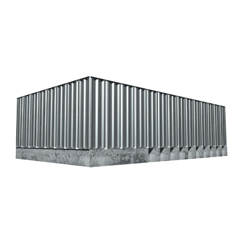
Tank material affects both project schedule and lifetime cost. Bolted stainless steel panels assemble without hot work, which matters on tight urban sites. Welded stainless steel gives the strongest corrosion control but requires certified welders on site. Galvanized and concrete tanks remain viable for very large reserves.
| Material | Typical capacity | Key advantage | Main limitation |
| Bolted stainless steel (304/316) | 2-2,500 m3 | Fast assembly, no site welding | Gasket maintenance |
| Welded stainless steel | 5-3,000 m3 | Superior corrosion control | Certified welders required |
| Hot-dip galvanized steel | 2-1,500 m3 | Cost-effective large storage | Coating repair in the field |
| Reinforced concrete | 50-10,000 m3 | Very large fixed reserves | Extended construction time |
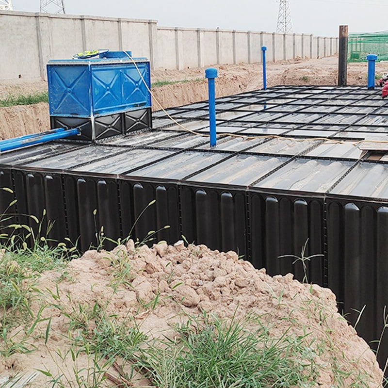
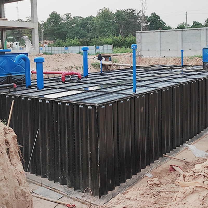
Underground and semi-buried tank arrangements reduce freeze risk and preserve site space, but the pump suction lift and the ventilation of the enclosure must be evaluated in the same hydraulic study.
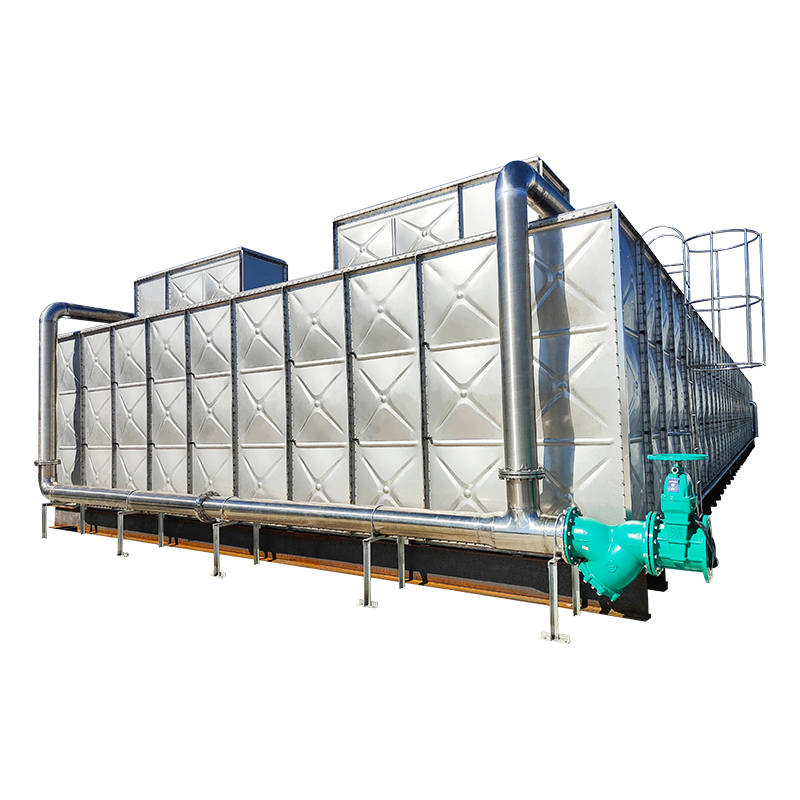
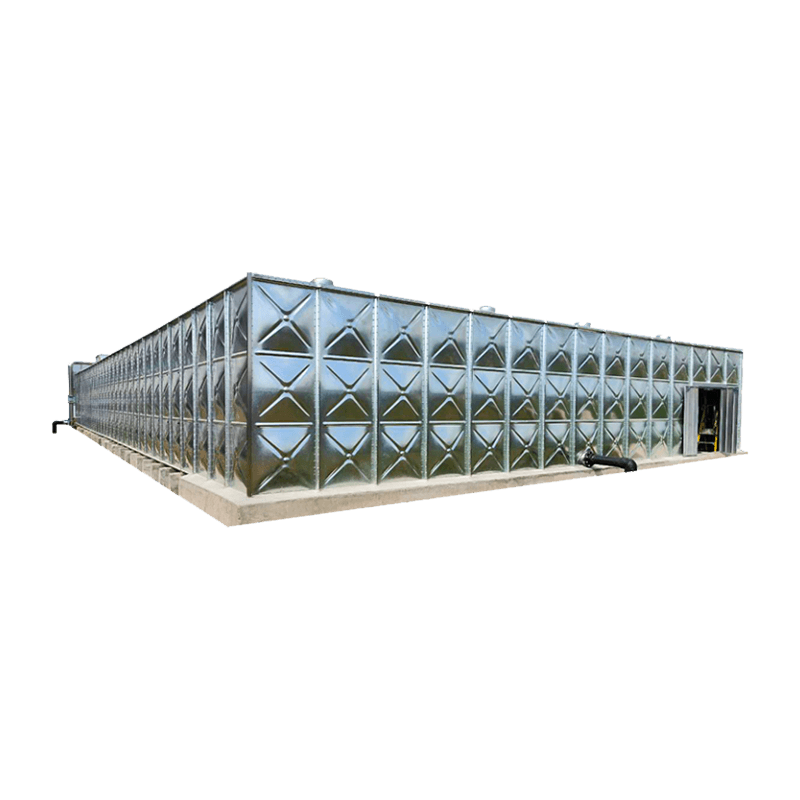
 Corrosion-Resistant Domestic and Fire Water Storage TankA rectangular metal tank built from stainless or galvanized steel, designed for reliable storage of domestic and fire-fighting water. Its sealed structure and large capacity make it suitable for supplying the required fire reserve volume in a sprinkler system.View Product →
Fire pumps are rated at the point where the system duty sits on the pump curve, and the manufacturer must certify the pump at 150% of rated flow while holding at least 65% of rated pressure. The same standard limits the churn pressure, the shut-off condition, to 140% of rated pressure. These two acceptance bands protect the piping and sprinkler fittings from both cavitation and overpressure.
The most frequently miscalculated parameter is net positive suction head. The tank outlet elevation, the suction pipe length, and the strainer loss determine whether the pump runs above its required NPSH. That is exactly the condition that caused the suction collapse in the opening test.
| Pump type | Flow range | Head range | Best application |
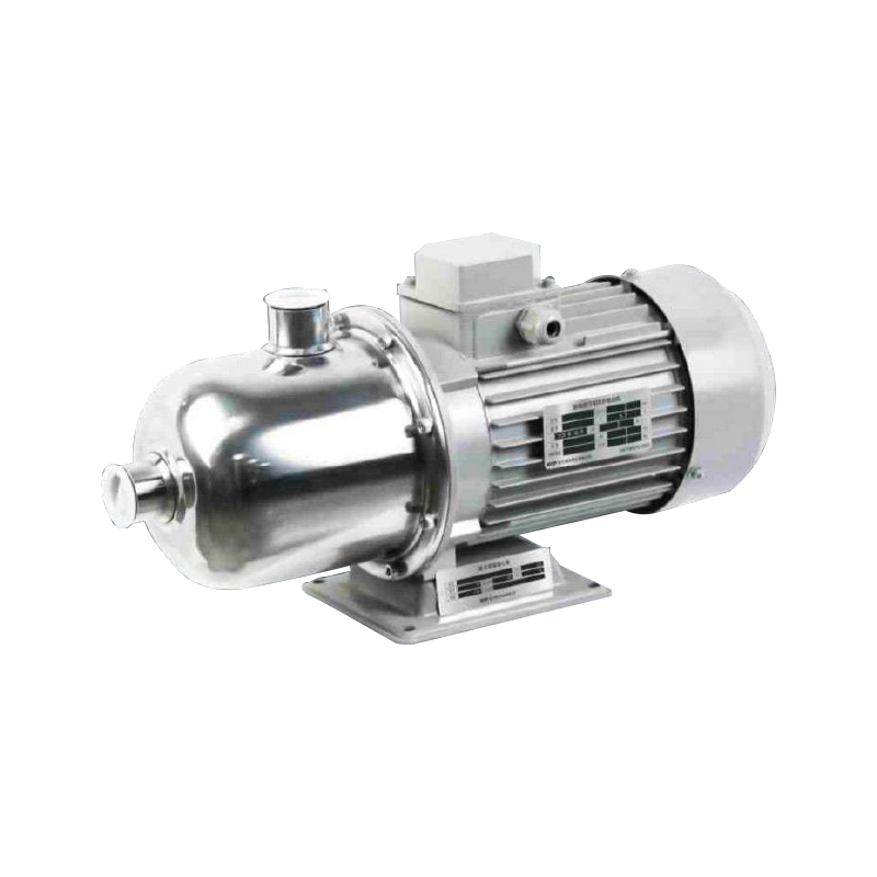
| Horizontal end suction | 2-200 L/s | Up to 160 m | Compact plant-room footprint |
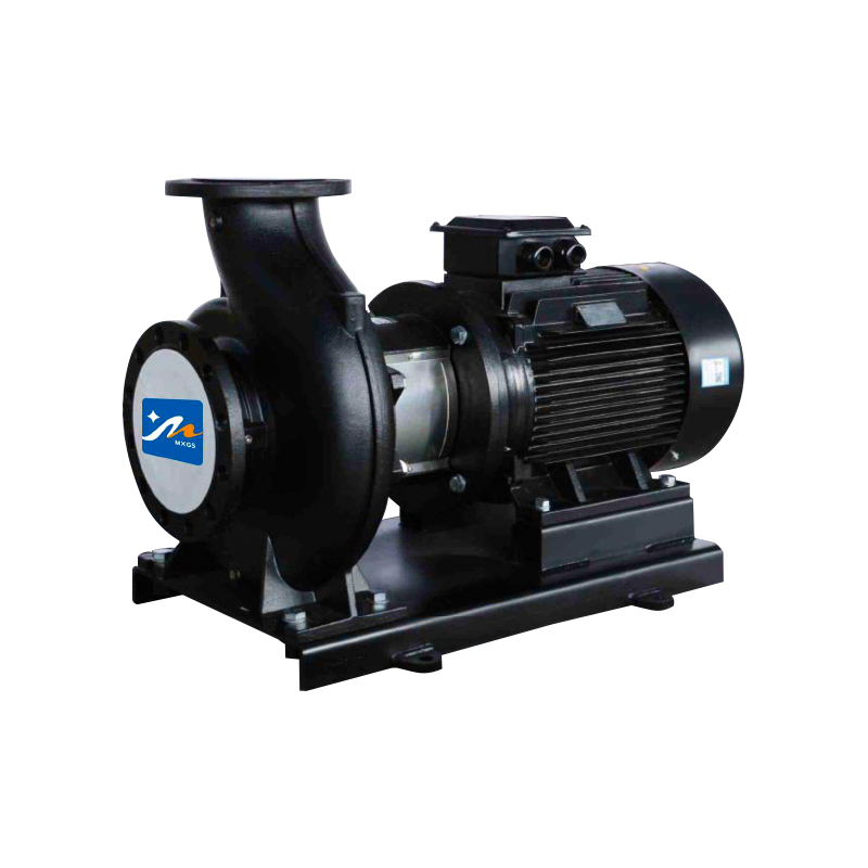
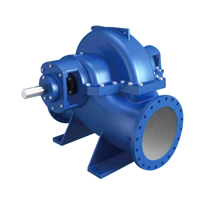
| Horizontal split case | 10-500 L/s | Up to 200 m | High-flow warehouse and industrial |
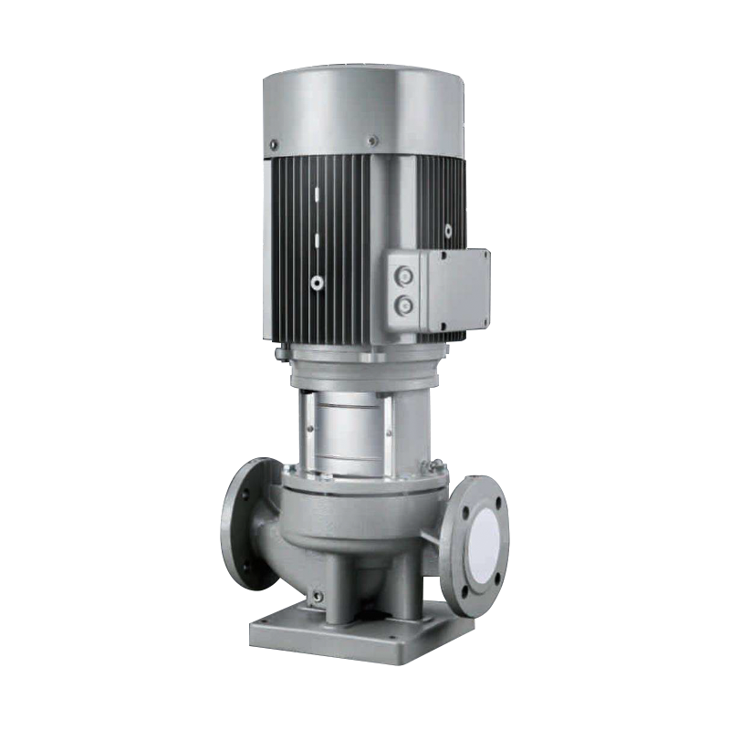
| Vertical multistage | 1-50 L/s | Up to 300 m | High-rise boosting and jockey duty |
Each configuration has a different space requirement and maintenance access pattern. The pump room must also allow the code-mandated clearance around the driver, the controller, and the suction manifold, because these clearances are checked at final inspection.
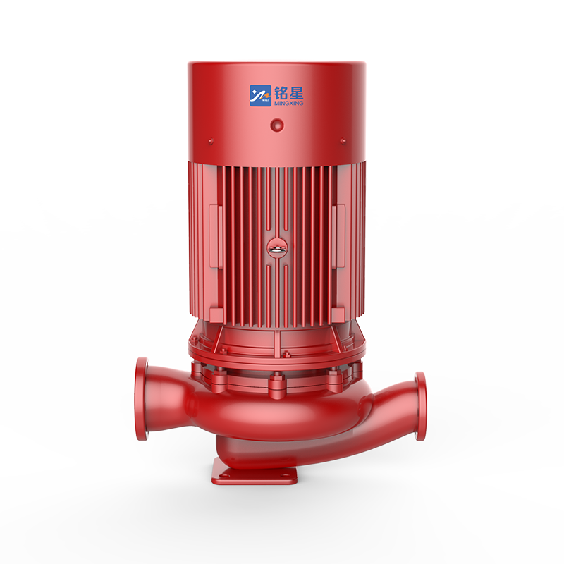 Factory-Assembled Vertical Fire Pump Set with CertificationThis vertical single-stage fire pump set is certified to GB 6245-2006 and includes corrosion-resistant impellers. Its compact, pre-tested assembly simplifies installation and helps meet the pump curve and pressure requirements discussed in the surrounding hydraulic design context.View Product →
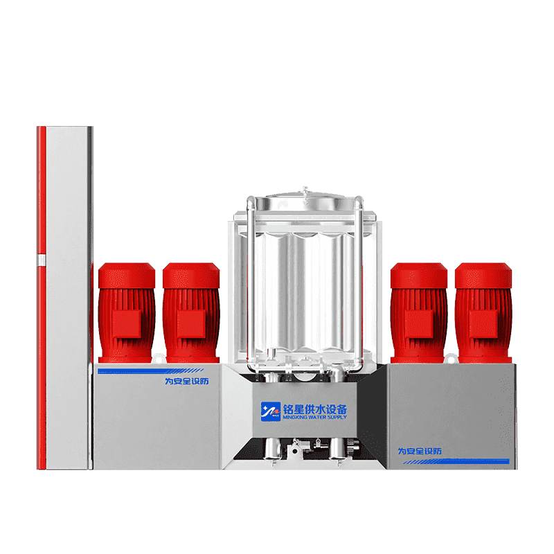
Factory-assembled fire pump stations combine the storage tank, pump sets, manifold, and control panel into one engineered package, reducing on-site installation from weeks to days. Because the assembly is hydraulically tested before dispatch, field piping errors largely disappear, and the owner deals with a single supplier for the hydraulic core.
Multiple subcontractors manage concrete, piping, electrical, and controls on site. Commissioning often reveals interface gaps, and the schedule depends on the slowest trade.
One manufacturer engineers and tests the complete package. On-site work is limited to set-down, flange connection, and the final fill test.
Flow, pressure, and duration are calculated against the project hazard class and local code.
Tank, skid, manifold, and control panel are produced to the approved drawing set.
A full-flow pump start sequence is witnessed before dispatch.
The station is set down, suction and discharge flanges connected, then re-tested.
A factory-built station also changes the cost structure: the engineering effort moves to the factory floor, where quality is measured, not discovered.
Final acceptance of a fire fighting water supply system depends on witnessed flow and pressure tests, not on design calculations. The owner should keep the pump curves, test certificates, and as-built drawings as the permanent record of the system capacity.
The checklist below covers the items most often flagged during fire authority inspections:
When questions arise about the pump curve or the storage volume, the design team should review as-built conditions instead of re-checking the calculation sheet. Contact the manufacturer's application engineers for curve validation and commissioning support.
Duration follows the occupancy hazard class: light hazard spaces generally need 30 minutes, ordinary hazards 60-90 minutes, and high-piled storage or process areas 2-4 hours. The local fire code sets the exact value, and the storage tank is then sized as flow x duration.
Yes, where the code permits a combined tank. The fire reserve must be protected so normal usage cannot draw it down - typically by placing the fire outlet below the domestic outlet and adding a lockable valve arrangement that prevents accidental depletion.
Fire codes treat the supply system as single-failure-tolerant. A 100% standby pump, or a second power source, maintains the required flow while the failed unit is repaired or replaced.
The pump must maintain the hydraulically calculated demand at the most remote sprinkler - often 0.5 bar or more for standard spray heads, with 6.9 bar required at fire department hose connections. The required pump discharge pressure equals that value plus elevation and friction losses, capped by the system pressure rating.
Related Products

Contact us
Headquater Address
Room 901, Building 17, Lane 1088, Shen Hong Road, Minhang District, Shanghai
Factory Address
No. 1, Mingxing North Road, Tech Innovation Park, Jianhu County, Yancheng, Jiangsu, P. R. China
Amy@mxwatersupply.com
Amy@mxwatersupply.com
Telephone(Whatsapp/Wechat)
+86-18051685983
QR CODE

 English
 Français