Sep 29, 2026
A 14-story apartment block closed its water-supply contract on a classic imbalance: the municipal main delivered 0.18 MPa at the property line, which is acceptable for the first six floors and nearly useless above the tenth. Between 7:00 and 9:00 PM, the top three floors received a trickle.
The developer needed booster water supply equipment and had to choose between proposals that disagreed on pump count, tank size, and connection method. That scene repeats on nearly every high-rise project. The decision becomes far easier when the equipment is treated as one hydraulic package, not as a single pump with accessories.
Content
Booster water supply equipment raises incoming pressure and holds it inside a stable band while the number of open taps changes by the second. It is an integrated assembly, not a single pump: two or three multistage centrifugal pumps, pressure transducers, a diaphragm accumulator, variable-frequency drives, valves, and a control cabinet on one skid.
At zero demand, the pumps are off and the diaphragm tank holds cut-out pressure. A tap opens, pressure falls to cut-in, and the lead pump starts at low VFD frequency. As demand rises, the drive speeds up; when the lead pump cannot hold the setpoint, the controller stages the second pump in. One measured value, discharge pressure, governs the whole cycle.
Core definition: a booster water supply system is an assembly of pumps, pressure sensing, variable-speed drives, and a pressure-maintenance tank that keep discharge pressure inside a defined band while demand varies.
A functional package always includes these components:
Design flow and required head are the only two numbers needed to start; motor power is the result of the calculation, never the starting point.
Design flow comes from fixture-unit tables or per-apartment demand. A 112-apartment tower with four water-use points per apartment peaks near 18 m3/h once diversity is applied, although the sum of all outlets exceeds 50. Using the non-diversified figure is the most common oversizing error.
Required head is static lift plus friction plus residual pressure at the highest fixture. For a 14-floor slab: static lift to the top fixture is about 43 m, friction adds 5 to 8 m, and codes ask for 10 to 15 m residual. The total is about 65 m. With 0.18 MPa (18 m) incoming, the booster must add roughly 47 m.
| Design flow, peak simultaneous | 18 m3/h |
| Static lift to highest fixture | 43 m |
| Friction allowance for risers and meters | 7 m |
| Residual pressure at top fixture | 15 m |
| Total required head at duty point | 65 m |
| Municipal inlet pressure available | 18 m |
| Net boost required | 47 m |
| Recommended pump set | Two duty plus one standby, 4 kW each |
Rule of thumb: every additional 10 m of building height adds close to 10 m (0.1 MPa) of required discharge pressure. Specifying for the top-floor fixtures alone is the classic under-design.
Every practical installation fits one of four arrangements; the measured inlet pressure and local code decide which one survives contact with reality.
The standard for high-rise residential and hotels. Two or three multistage pumps run under one pressure setpoint, each with a VFD, and the controller alternates duty and standby weekly. This configuration delivers the tightest pressure band and the lowest part-load energy draw. Jiangsu Mingxing Water Supply Equipment Co., Ltd. packages this arrangement as a single pre-wired skid with matched controls.
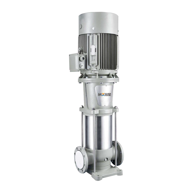
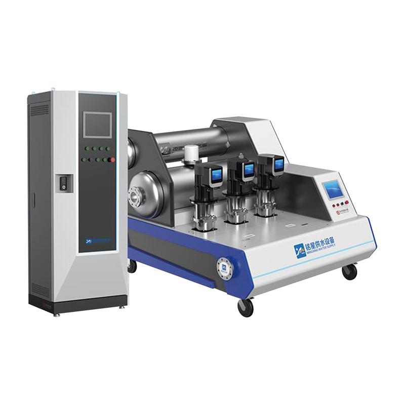 VFD Controlled Constant Pressure Booster System with Pre-Wired SkidThis system combines multiple multistage pumps with individual VFDs and alternating duty/standby control for tight pressure regulation. It suits high-rise residential and hotel projects, offering low part-load energy draw as a pre-assembled package.View Product →
Used where the municipal main is strong but the utility forbids starving the network. The pump takes suction from the main through a small compensation tank; when inlet pressure falls below about 0.10 MPa, the controller switches to bypass or tank-fed mode. This is the dominant configuration for dense urban sites without space for a storage tank.
The pump draws from an atmospheric storage tank. This decouples the building from the main, guarantees a fixed suction level, and suits combined domestic-plus-fire storage. The trade-offs are footprint, an extra pumping stage, and tank cleaning duty.
The simplest form draws straight from the main without negative-pressure compensation, and only where the main is oversized for the project and pressure stays stable. Utilities typically restrict it to smaller buildings.
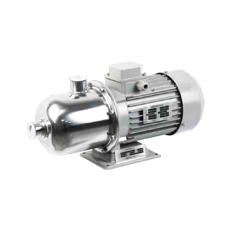
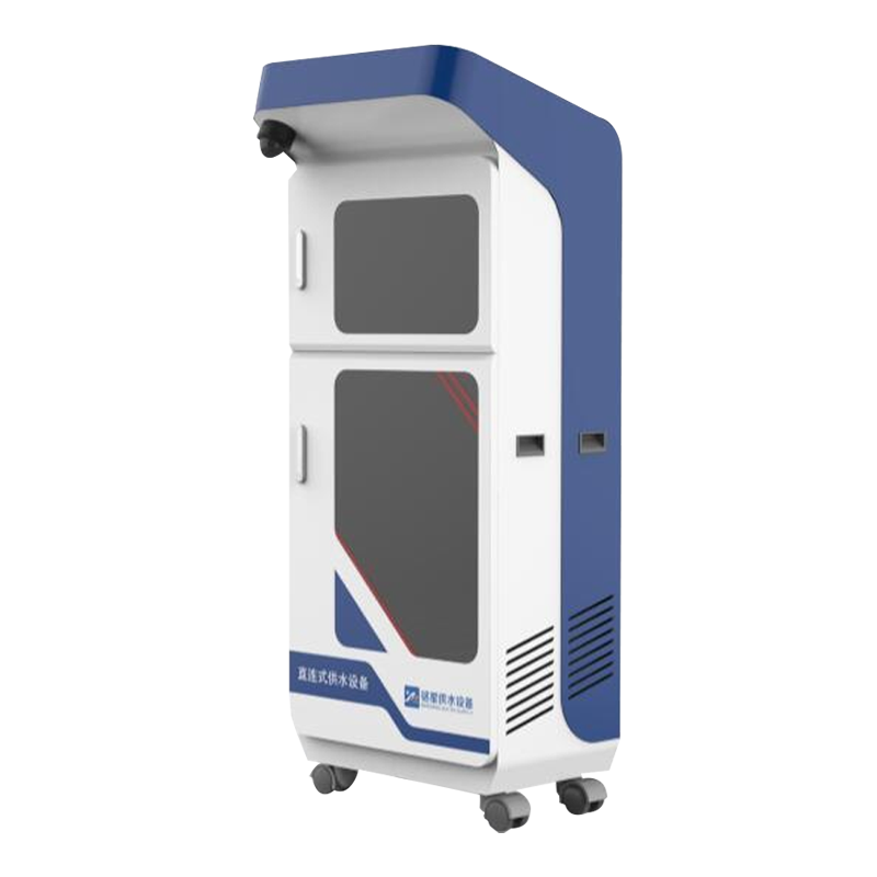 Direct Connection Water Supply Equipment with 304 Stainless Steel CabinetDesigned for direct main connection in smaller buildings, this equipment features outdoor-rated IP55 protection, modular installation, and remote monitoring. It dynamically adjusts flow and pressure to save energy, suitable for rural and urban water supply upgrades.View Product →
| Configuration | Water source | Stability | Energy | Main risk | Best use |
| VFD constant-pressure | Main or break tank | 0.01-0.02 MPa band | High | VFD cost, harmonics | High-rise residential, hotels |
| Tank-type non-negative-pressure | Main via compensation tank | 0.02-0.03 MPa band | High | Inlet drop below 0.10 MPa | Dense urban mid- and high-rise |
| Break-tank booster | Atmospheric tank | Very stable | Medium-high | Tank hygiene, footprint | Commercial, combined fire and domestic |
| Direct-connection | Municipal main | Depends on main | Medium | Low-pressure cut-off trips | Small buildings, stable mains |
Key takeaway: non-negative-pressure equipment does not fix a weak main; it lets a strong main feed the building through a regulated suction path. Set the inlet cut-off from a 24-hour logged measurement, not from a utility nominal figure.
Water hammer, short cycling, and air-bound suction account for most post-commissioning failure tickets; all three are selected on paper, not discovered on site.
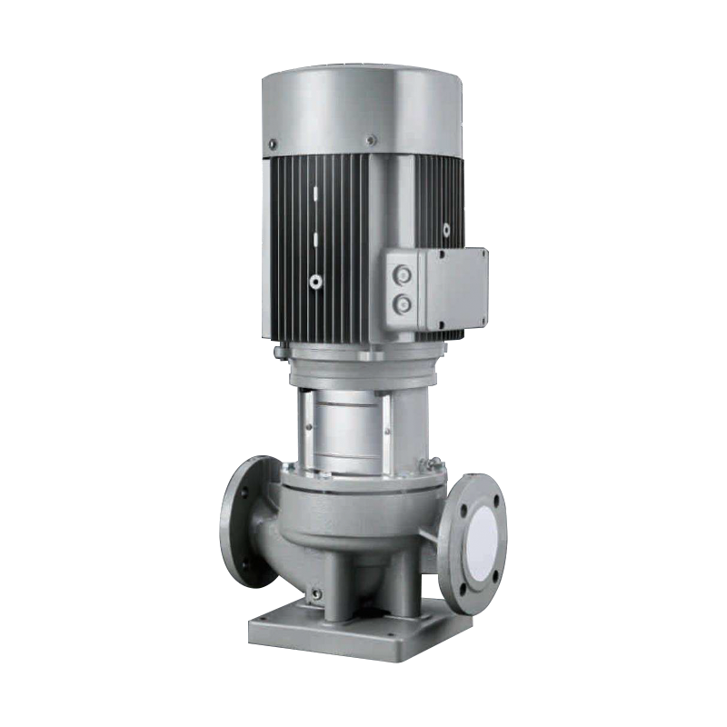
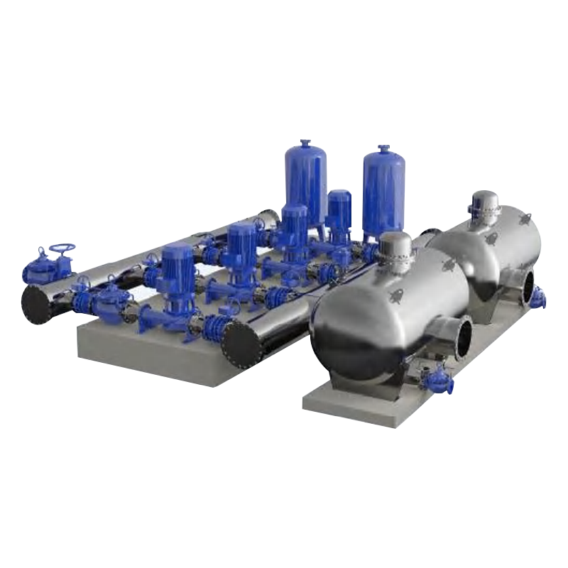 Digital Fully Variable-Frequency Tank-Type Non-Negative Pressure Pump StationThis tank-based station prevents negative pressure on municipal mains while maintaining constant pressure output. Full frequency conversion, intelligent monitoring, and low-flow shutdown features reduce energy use and extend equipment life, addressing water hammer and short cycling issues.View Product →
Field note: in one hotel project, the top-floor shower flow collapsed whenever the kitchen dishwasher ran. The cause was a 30-second VFD ramp rate; cutting it to 5 seconds and enabling second-pump stagger restored full function with no hardware change.
A VFD-controlled booster plant commissioned with recorded parameters uses 30 to 50 percent less energy than a constant-speed plant with a throttled valve, but only when the settings are actually applied.
Commissioning fixes the operating band the building will live with for a decade. The steps that matter:
Maintenance follows a simple rhythm: monthly visual checks for leaks and noise; quarterly checks of accumulator pre-charge, normally 70 percent of cut-in pressure; annual calibration of the pressure transducer and inspection of check valves. A maintenance contract or site audit pays back when the plant room is remote and no resident technician exists.
A pressure setpoint raised by only 5 m adds roughly 7 to 9 percent to the annual pumping energy bill and accelerates seal and bearing wear.
No. A single pump raises pressure; the equipment adds the pressure sensor, variable-frequency drive, accumulator, alternation logic, and safety cut-offs that keep pressure stable while demand changes. Buying only a pump leaves the stabilization problem unsolved.
Only with non-negative-pressure or direct-connection equipment approved by the local water utility, and only when a 24-hour logged test shows the inlet pressure stays above the equipment cut-off. Below that threshold, the system must draw from a storage tank.
Between 0.40 and 0.55 MPa at the discharge manifold covers most buildings up to 18 floors. Above that height, zone the system or install intermediate break tanks. Domestic fixtures are rated for about 0.55 MPa maximum, so lower floors may need pressure-reducing stations.
Correct the pump size or trim the impeller, check that the accumulator pre-charge is close to 70 percent of cut-in pressure, and program the VFD minimum frequency, typically 25 Hz, below which the pump switches off.
Bottom line: correct sizing, a measured inlet profile, and VFD-based pressure control solve 90 percent of booster water supply equipment problems in the field.
Related Products

Contact us
Headquater Address
Room 901, Building 17, Lane 1088, Shen Hong Road, Minhang District, Shanghai
Factory Address
No. 1, Mingxing North Road, Tech Innovation Park, Jianhu County, Yancheng, Jiangsu, P. R. China
Amy@mxwatersupply.com
Amy@mxwatersupply.com
Telephone(Whatsapp/Wechat)
+86-18051685983
QR CODE

 English
 Français