Sep 24, 2026
At 7:12 a.m. in a 12-story residential building, the shower on the tenth floor turns cold for four seconds whenever a washing machine on the third floor opens its inlet valve. The discharge gauge swings more than 0.15 MPa between draw-off peaks because a fixed-speed pump is cycling on and off instead of modulating its output. A constant pressure water supply system ends that failure mode by holding pressure inside a narrow setpoint band, and it cuts the energy wasted by throttled or cycling pumps.
For an engineer or developer, the term describes a specific engineering package, not a marketing label. Jiangsu Mingxing Water Supply Equipment Co., Ltd. designs and builds these systems with IoT control and multi-pump sequencing. The questions that matter are pressure accuracy, energy data, tank decisions, and code compliance. This article answers them with figures that apply at the specification stage.
Content
Pressure stability is the product, and the limit is +/-2% at the discharge header. Fixed-speed pumps with a pressure switch work inside a 0.08 to 0.12 MPa hysteresis band - the swing that causes cold bursts and riser water hammer. Residential towers run at 25 to 35% of design flow, so a fixed-speed pump cycles dozens of times per hour and wears out relays in under two years.
Three outputs define whether a system works: the pressure band under transient load, energy draw at partial flow, and starts per hour. A correctly designed system holds +/-2%, draws 30 to 50% less power than a throttled fixed-speed set, and starts fewer than 10 times per hour by sleeping at low demand.
The system maintains pressure by reading the discharge header every 10 to 20 ms, comparing it with the setpoint, and adjusting pump speed through a PID loop inside the VFD. The sequence has five steps.
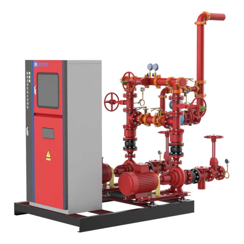
Jiangsu Mingxing builds this logic into its VFD-controlled constant pressure booster system, with multi-pump sequencing, PID pre-tuning, and low-flow sleep included. Tuning guidance is covered in the article on how VFD improves the operational stability of constant pressure boosting systems.
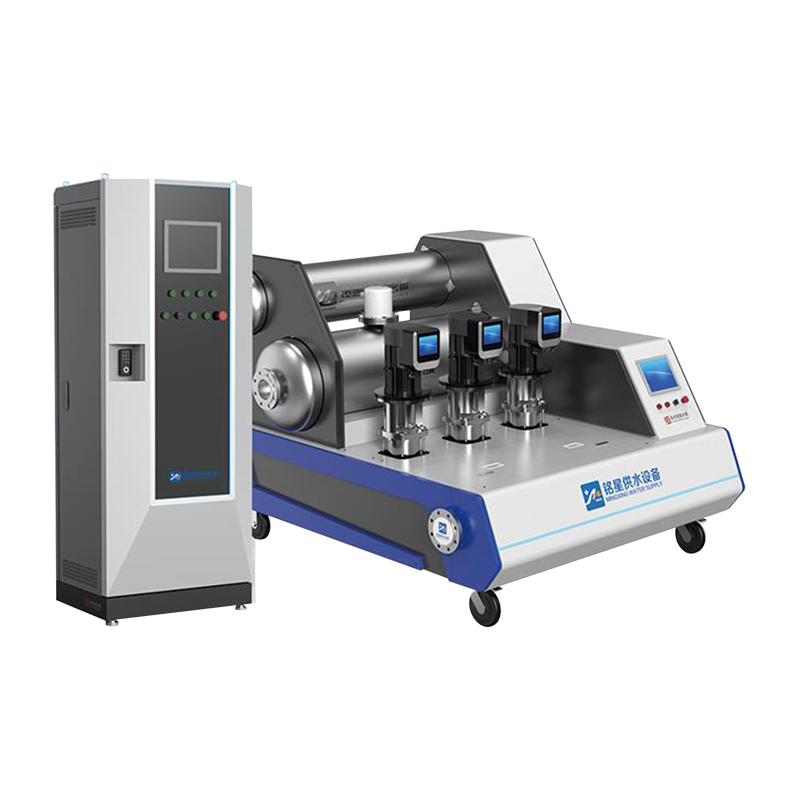 VFD-Controlled Constant Pressure Booster System with Multi-Pump SequencingThis packaged booster system integrates multiple pumps, VFD control, PID pre-tuning, and low-flow sleep. It fits the article's selection logic for high-rise buildings, offering pressure-constant water supply with commissioning guidance for design verification.View Product →
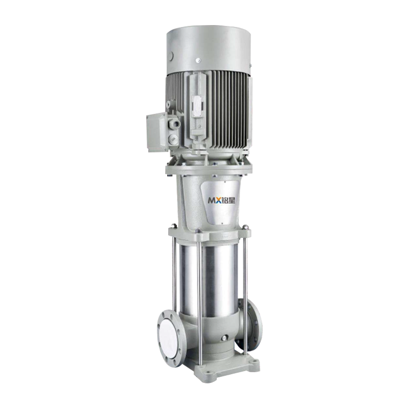
Selection starts with the demand curve, not the pump curve. First, calculate design flow from fixture units using the Hunter curve or the GB 50015 method; a 12-story building with 120 apartments lands between 8 and 12 L/s. Second, calculate total head as static lift plus friction plus a 0.10 to 0.15 MPa residual tap pressure. At 48 m static lift and 12 m friction, design head is about 75 m, so a vertical multistage centrifugal pump is the right choice.
Third, map night-time minimum flow. A building drawing 3 to 5% of design flow between midnight and 5 a.m. will destroy a pump set that cannot sleep or run a jockey pump. The topology decision comes after the demand curve, not before it.
| Design parameter | VFD tankless booster | Break-tank system | No-negative-pressure system |
| Pressure band at fixture | +/-2% of setpoint | +/-3 to 5% | +/-2% |
| Energy saving vs throttled pump | 30 to 50% | 20 to 35% | 30 to 50% |
| Footprint at 10 L/s duty | about 2.5 sq m | 6 to 8 sq m plus tank | about 3 sq m |
| Suction requirement | Reliable suction source | Municipal fill line | Municipal direct connection |
| Best application | High-rise residential, hotels | Unreliable intake areas | Stable city mains |
A VFD-driven constant pressure water supply system draws 28 to 50% of rated power at partial flow, while a throttled fixed-speed pump draws more than 90% at the same flows. The chart below plots typical measurements from residential booster installations with a fixed discharge setpoint.
At 40% flow, the throttled pump needs 92% of rated power and the VFD system about 30%. At 70% flow, the figures are 94% and 50%. Both reach 100% at full flow. In a building below 70% flow for most running hours, the weighted saving lands in that range. On a 22 kW booster running 5,000 hours a year, a 40% saving is 44,000 kWh, or about USD 5,300 at USD 0.12 per kWh.
Most underperforming constant pressure systems fail because of wrong transducer placement, a missing low-flow strategy, or a suction source that cannot feed the pump. Four mistakes account for nearly all commissioning complaints.
Water stagnation is becoming a code issue in several provinces. Jiangsu Mingxing addresses it with variable-frequency water supply equipment with a water quality improvement function, which adds timed circulation and residual monitoring to the constant pressure package.
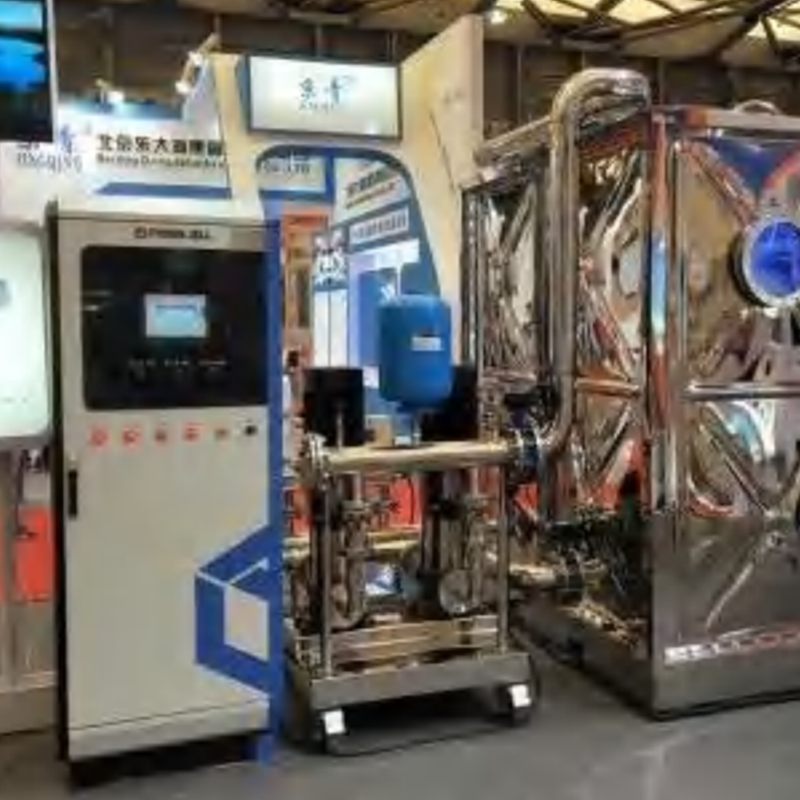 Variable Frequency Water Supply Equipment with Water Quality ImprovementThis variable-frequency water supply unit adds timed circulation and residual monitoring to address water stagnation. Its purification tank uses fine-pore filters, activated carbon, and UV sterilization to reduce impurities and bacteria, making it suitable for code-driven water quality requirements.View Product →
Commissioning proves the design. A disciplined handover takes four steps.
Choose the topology by the water source, not the pump set. Municipal reliability, inlet pressure, and code restrictions on direct pumping decide whether a tankless booster, a break-tank system, or a no-negative-pressure system is correct.
A no-negative-pressure system adds a compensating tank and a control loop that keeps suction pressure above a floor value, typically 0.10 MPa. Jiangsu Mingxing's digital full-frequency conversion voltage-stabilizing tank-type without negative pressure packages the compensator, pumps, VFDs, and controller as one unit.
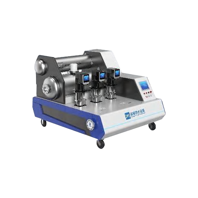 Digital Full Frequency Conversion Pressure-Stabilizing Tank-Type Non-Negative Pressure EquipmentThis integrated unit packages a constant-flow food-grade stainless steel tank, booster pumps, VFDs, vacuum suppressor, and controller. It eliminates negative pressure on municipal networks via CAN bus independent pump control, supporting throttled suction pressure and break-tank fallback for unreliable supplies.View Product →
Break-tank topology is the fallback when the municipal supply is too unreliable; size the tank for at least 15 minutes of design flow and start the booster before the tank empties.
Constant speed runs fixed-speed pumps against a pressure switch, so discharge pressure oscillates inside a 0.08 to 0.12 MPa band. Constant pressure modulates a VFD to hold a fixed setpoint continuously, keeping pressure flat within +/-2%.
Documented savings in partial-load applications are 30 to 50% against throttled fixed-speed operation, because power demand drops with the cube of speed. Buildings below 70% flow for most operating hours see the top of that range.
The tank covers minimum flow and thermal expansion, not main storage. For a 10 L/s duty with 5% minimum flow, a 50 to 100 L diaphragm tank is normally enough; with VFD sleep mode, it only needs to cover the 10 to 30 seconds before restart.
Yes, if the pumps are healthy and the panel can accept a VFD. The retrofit adds a transducer, a PID control panel, and a small expansion tank, and usually keeps the existing pumps.
Related Products

Contact us
Headquater Address
Room 901, Building 17, Lane 1088, Shen Hong Road, Minhang District, Shanghai
Factory Address
No. 1, Mingxing North Road, Tech Innovation Park, Jianhu County, Yancheng, Jiangsu, P. R. China
Amy@mxwatersupply.com
Amy@mxwatersupply.com
Telephone(Whatsapp/Wechat)
+86-18051685983
QR CODE

 English
 Français